
.jpg)
.jpg)
.jpg)
.jpg)
.jpg)
.jpg)
.jpg)
.jpg)
.jpg)
.jpg)
.jpg)
.jpg)
.jpg)
.jpg)
.jpg)
.jpg)
Installation Instructions
& Deadbolt Usage, Cleaning, Service Bulletins, Missing Accessories, Sample Finishes
TABLE OF CONTENTS
A. Back-to-Back, Paired Installation InstructionsAffected Models: Carnegie, Carnegie (Engraved), Eisenhower, Hamilton, Madison, Vanderbilt
Affected Part Numbers: KT3001, KT3001-C1, KT3119, KT2630, KT3061, KT3254 B. Back-to-Back, Paired Installation Instructions
Affected Models: Oppenheimer, Rockefeller, Rockefeller (Engraved), Roosevelt
Affected Part Numbers: KT2373, KT3014, KT3014-C2, KT3015 C. Single-Sided, Door Application Installation Instructions
Affected Models: Carnegie (Single-Sided), Madison (Single-Sided)
Affected Part Numbers: KT3001-S, KT3061-S D. Single-Sided, Door Application Installation Instructions
Affected Models: Rockefeller (Single-Sided)
Affected Part Numbers: KT3014-S E. Single-Sided, Wall (Towel Bar) Application Installation Instructions
Affected Models: Carnegie (Single-Sided), Madison (Single-Sided)
Affected Part Numbers: KT3001-S, KT3061-S F. Single-Sided, Wall (Towel Bar) Application Installation Instructions
Affected Models: Rockefeller (Single-Sided)
Affected Part Numbers: KT3014-S G. How to “Catch & Latch“ a door with “Roller Catches” & Other Types & Deadbolt Usage H. Stainless Steel Care & Cleaning Instructions I. Technical Service Bulletins J. Missing Accessories (Purchase Replacement Kits) K. Sample Plate-Ring for Different Finishes
A. KeyTiger Back-to-Back, Paired Installation Instructions
AFFECTED MODELS/PART NUMBERS: Carnegie (KT3001) Carnegie (Engraved) (KT3001-C1) Eisenhower (KT3119) Hamilton (KT2630) Madison (KT3061) Vanderbilt (KT3254)KeyTiger Youtube Channel: https://goo.gl/1qcUIt
WARNING: Never remove the necks/standoffs on the handles. They are mounted to each bar via a 5.0mm
socket-head bolt. It is unnecessary to remove these socket-head bolts to install the handles. Removing them may
cause unwanted damages to the handle.
HINT: All accessories are provided to install these handles. If they are not provided, please note that you
do NOT need to disassemble that particular subassembly and could damage the handles by doing so.
-
A-1. Sizing up Bolt lengths to Door Thickness
- Most designs come with multiple mounting bolts of different lengths. The shorter bolts are typically for glass doors and the longer bolts are typically for thick wooden doors or gates.
- Using the allen wrench provided, remove the 2 small set screws located on each neck/standoff of the handle. This will cause the pair of handles to be disconnected from one another. It is recommended to take a picture of the arrangement of the components at this point to ease reinstallation later.
- Using a Phillips screwdriver, untighten both of the exposed Phillips bolts until they fully unthread but RETHREAD it back in 1 full revolution as soon as it unthreads without dropping any of the assembled components. This is to set up the spacing between the washers to size up the bolt length to the door thickness.
- When the Phillips bolts are threaded 1 revolution in, distance the 2 off-white Nylon washers as much as possible to each side of the bolt – the door will be mounted with the Nylon washers on each side.
- Align this door handle assembly to the door you intend to install on making sure the door thickness is less than the space available between the Nylon washers. If so, continue to the next step. If not, remove both Phillips bolts and install the longer versions of the bolt provided making sure that the door thickness fits between these 2 Nylon washers with the longer bolts. Be careful to remember the arrangement of the components as you change bolts.
- Each hole should be more than the diameter of the threaded bolt and less than the diameter of the bolt head. Typically, a diameter of 0.315 – 0.600 inches (1/2″ or .500″ is recommended) should work but always verify by measurements.
- Use the Center-to-Center mounting distances provided on the table on each product page for reference. These numbers provided do not include tolerances so it is always necessary to drill on actual measurements of the handle in possession for locating purposes.
- Mark the points of the 2 holes on the wall and use an angle level sensor to ensure the straight line is not tilting.
- Drill the appropriate hole size with the correct center distances on your door. A-3. Installing the Side of the Handle Without the Set Screws First
- Refer to images above & below for the arrangement of the components on the necks/standoffs. The door will be sitting between Nylon Washer #1 and #2.
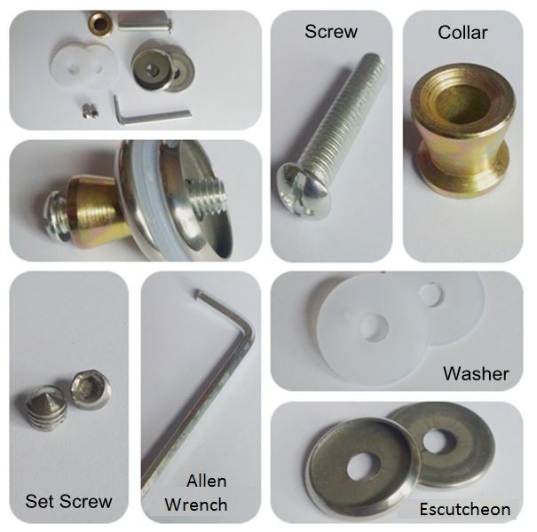
- Install the subassembly onto the door, arranging the accessories in the correct order: Door | Nylon washer | Escutcheon | Collar | Bolt.
- On the other side of the door, insert the nylon washer, escutcheon, followed by the handle that does not use set screw (this side has threaded necks).
- Thread the Phillips bolt until it bottoms out ensuring the collar is flushed with the head of the bolt. Do this for both necks. A-4. Installing the Opposite Side of the Handle
- Align the remaining handle (set screw side) to the 2 protruding bolts. Ensure that both handles are aligned appropriately to the escutcheons and nylon washers. Adjust as necessary by backing out and centering both Phillips bolt head.
- Tighten down both set screws EVENLY to center the handle. This requires tightening each set screw at 1 revolution at a time – alternating between one screw and the other until both screws bottom out. This allows the handle to be CENTERED.
ANNOTATED COMPONENTS ARRANGED IN INSTALLATION ORDER


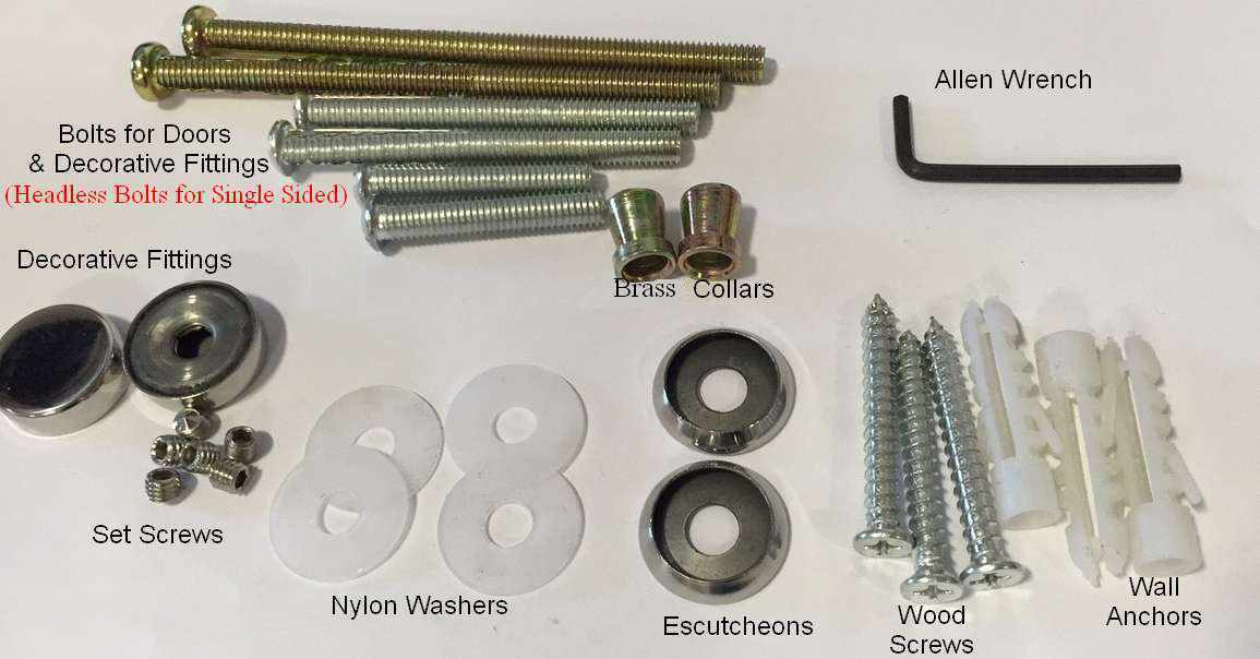
INCLUDED ACCESSORIES
B. KeyTiger Back-to-Back, Paired Installation Instructions
AFFECTED MODELS/PART NUMBERS: Oppenheimer (KT2373) Rockefeller (KT3014) Rockefeller (Engraved) (KT3014-C2) Roosevelt (KT3015)KeyTiger Youtube Channel: https://goo.gl/1qcUIt
- B-1. Sizing up Bolt lengths to Door Thickness
- Most designs come with multiple mounting bolts of different lengths. The shorter bolts are typically for glass doors and the longer bolts are typically for thick wooden doors or gates.
- Using a Phillips-head screw driver, remove the 4 machine screws located on end of the handle. This will cause the pair of handles to be disconnected from one another. It is recommended to take a picture of the arrangement of the components at this point to ease reinstallation later.
- Using a Phillips screwdriver, untighten both of the exposed Phillips bolts until they fully unthread but RETHREAD it back in 1 full revolution as soon as it unthreads without dropping any of the assembled components. This is to set up the spacing between the washers to size up the bolt length to the door thickness.
- When both Phillips bolts are threaded 1 revolution in, distance the 2 off-white Nylon washers as much as possible to each side of the bolt – the door will be mounted with the Nylon washers on each side.
- Align this door handle assembly to the door you intend to install on making sure the door thickness is less than the space available between the Nylon washers. If so, continue to the next step. If not, remove both Phillips bolts and install the longer versions of the bolt provided making sure that the door thickness fits between these 2 Nylon washers with the longer bolts. Be careful to remember the arrangement of the components as you change bolts. B-2. Drilling Thru-Holes
- Each hole should be more than the diameter of the threaded bolt and less than the diameter of the bolt head. Typically, a diameter of 0.315 – 0.600 inches (1/2″ or .500″ is recommended) should work but always verify by measurements.
- Use the Center-to-Center mounting distances provided on the table on each product page for reference. These numbers provided do not include tolerances so it is always necessary to drill on actual measurements of the handle in possession for locating purposes.
- Mark the points of the 2 holes on the wall and use an angle level sensor to ensure the straight line is not tilting.
- Drill the appropriate hole size with the correct center distances on your door. B-3. Installing the Side of the Handle With the Threads First
- Install the subassembly onto the door, arranging the accessories in the correct order: Door | Nylon washer | Stamped Insert | Bolt.
- On the other side of the door, insert the nylon washer, followed by the handle that does not use the small machine Phillips screws (this side has female threads on each end of the handle).
- Thread the Phillips bolt until it bottoms out. B-4. Installing the Opposite Side of the Handle With Small Machine Phillips Screws
- Align the remaining handle to the 2 protruding bolts & stamped inserts. Ensure that both handles are aligned appropriately to the nylon washers. Adjust as necessary by backing out and centering both Phillips bolts.
- Tighten down all 4x machine Phillips screws.
C. KeyTiger Single-Sided, Door Application Installation Instructions
AFFECTED MODELS/PART NUMBERS: Carnegie (Single-Sided) (KT3001-S) Madison (Single-Sided) (KT3061-S)KeyTiger Youtube Channel: https://goo.gl/1qcUIt
WARNING: Never remove the necks/standoffs on the handles. They are mounted to each bar via a 5.0mm
socket-head bolt. It is unnecessary to remove these socket-head bolts to install the handles. Removing them may
cause unwanted damages to the handle.
HINT: All accessories are provided to install these handles. If they are not provided, please note that you
do NOT need to disassemble that particular subassembly and could damage the handles by doing so.
-
C-1. Sizing up Bolt lengths to Door Thickness
- Most designs come with multiple HEADLESS mounting bolts of different lengths. The shorter headless bolts are typically for glass doors and the longer headless bolts are typically for thick wooden doors or gates.
- Using the allen wrench provided, remove the 2 small set screws located on each neck/standoff of the handle. This will cause some pre-assembled components to be disconnected from the handle. It is recommended to take a picture of the arrangement of the components at this point to ease reinstallation later.
- Untighten the headless bolts until they fully unthread from the decorative fitting but RETHREAD it back in 1 full revolution back into the supplied decorative fittings. You may adjust the threaded collar as well to see allow the appropriate gap. This is to set up the spacing between the washers to size up the bolt length to the door thickness.
- Distance the 2 off-white Nylon washers as much as possible to each side of the threaded collar & decorative fitting – the door will be mounted with the Nylon washers on each side.
- Align this subassembly to the door you intend to install on making sure the door thickness is less than the space available between the Nylon washers. Adjust the threaded collar as necessary. If so, continue to the next step. If not, remove the headless bolts and install the longer versions of the bolt provided making sure that the door thickness fits between these 2 Nylon washers with the longer bolts. Be careful to remember the arrangement of the components as you change bolts. C-2. Drilling Thru-Holes
- Each hole should be more than the diameter of the headless threaded bolt and less than the diameter of the collar. Typically, a diameter of 0.315 – 0.600 inches (1/2″ or .500″ is recommended) should work but always verify by measurements.
- Use the Center-to-Center mounting distances provided on the table on each product page for reference. These numbers provided do not include tolerances so it is always necessary to drill on actual measurements of the handle in possession for locating purposes.
- Mark the points of the 2 holes on the wall and use an angle level sensor to ensure the straight line is not tilting.
- Drill the appropriate hole size with the correct center distances on your door. C-3. Installing the Handle
- Install the headless bolt onto the decorative fitting, place a washer onto it and place thru the drilled hole.
- On the other side of the door arrange the components as follows: Door | Nylon washer | Escutcheon | Threaded Collar.
- Tighten down until secure onto door. Do this for both necks.
- Align the handle to the 2 protruding collars.
- Tighten down both set screws EVENLY to center the handle. This requires tightening each set screw at 1 revolution at a time – alternating between one screw and the other until both screws bottom out. This allows the handle to be CENTERED. C-4. Using Wood Screws to “Blind” Mount Single-Sided Pull to Non-Glass Doors
- Wood screws may be used to mount the pull onto the doors such as wooden entry doors. No decorative fitting is used on this method.
- The self-drilling wood screws will be screwed into the wooden door with a screw driver.
- For wood entry doors, this method will require that the wood screw does not break thru and show on the opposite side of the door as it will not be visually pleasing. Depending on the door thickness, the supplied wood screws may or may not work for your application – you would have to measure by setting up the components to visually inspect. If the supplied wood screws do not work (only 1 length is provided), you may have to procure the appropriate length wood screws that do not break thru the other side of the door and still fits thru the accessories – thread type does not matter (metric or inches).
SINGLE-SIDED ACCESSORIES (CARNEGIE)
SINGLE-SIDED ACCESSORIES (MADISON)

D. KeyTiger Single-Sided, Door Application Installation Instructions
AFFECTED MODELS/PART NUMBERS: Rockefeller (Single-Sided) (KT3014-S)KeyTiger Youtube Channel: https://goo.gl/1qcUIt
-
D-1. Sizing up Bolt lengths to Door Thickness
- Most designs come with multiple HEADLESS mounting bolts of different lengths. The shorter headless bolts are typically for glass doors and the longer headless bolts are typically for thick wooden doors or gates.
- Using the Phillips screwdriver, remove the 4 small Phillips machine screws located on each ends of the handle. This will cause some pre-assembled components to be disconnected from the handle. It is recommended to take a picture of the arrangement of the components at this point to ease reinstallation later.
- Untighten the headless bolts until they fully unthread from the decorative fitting but RETHREAD it back in 1 full revolution back into the supplied decorative fittings. You may adjust the supplied M8x1.25 nut as well to see allow the appropriate gap. This is to set up the spacing between the washers to size up the bolt length to the door thickness.
- Distance the 2 off-white Nylon washers as much as possible to each side of the nut & decorative fitting – the door will be mounted with the Nylon washers on each side.
- Align this subassembly to the door you intend to install on making sure the door thickness is less than the space available between the Nylon washers. Adjust the nut as necessary. If so, continue to the next step. If not, remove the headless bolts and install the longer versions of the bolt provided making sure that the door thickness fits between these 2 Nylon washers with the longer bolts. Be careful to remember the arrangement of the components as you change bolts. D-2. Drilling Thru-Holes
- Each hole should be more than the diameter of the headless threaded bolt and less than the stamped insert. Typically, a diameter of 0.315 – 0.600 inches (1/2″ or .500″ is recommended) should work but always verify by measurements.
- Use the Center-to-Center mounting distances provided on the table on each product page for reference. These numbers provided do not include tolerances so it is always necessary to drill on actual measurements of the handle in possession for locating purposes.
- Mark the points of the 2 holes on the wall and use an angle level sensor to ensure the straight line is not tilting.
- Drill the appropriate hole size with the correct center distances on your door. D-3. Installing the Handle
- Install the headless bolt onto the decorative fitting, place a washer onto it and place thru the drilled hole.
- On the other side of the door arrange the components as follows: Door | Nylon washer | Stamped Insert | Nut.
- Tighten down until secure onto door. Do this for both necks.
- Align the handle to the 2 protruding stamped inserts.
- Tighten down all Phillips machine screws. D-4. Using Wood Screws to “Blind” Mount Single-Sided Pull to Non-Glass Doors
- Wood screws may be used to mount the pull onto the doors such as wooden entry doors. No decorative fitting is used on this method.
- The self-drilling wood screws will be screwed into the wooden door with a screw driver.
- For wood entry doors, this method will require that the wood screw does not break thru and show on the opposite side of the door as it will not be visually pleasing. Depending on the door thickness, the supplied wood screws may or may not work for your application – you would have to measure by setting up the components to visually inspect. If the supplied wood screws do not work (only 1 length is provided), you may have to procure the appropriate length wood screws that do not break thru the other side of the door and still fits thru the accessories – thread type does not matter (metric or inches).
SINGLE-SIDED ACCESSORIES (ROCKEFELLER)

E. KeyTiger Single-Sided, Wall (Towel Bar) Application Installation Instructions
AFFECTED MODELS/PART NUMBERS: Carnegie (Single-Sided) (KT3001-S) Madison (Single-Sided) (KT3061-S)KeyTiger Youtube Channel: https://goo.gl/1qcUIt
-
E-1. Drilling Thru-Holes & Installing Wall Anchors
- Ensure that the intended wall can be drilled – check with your installer for advice. Wall thickness must be at least 1/2″ thick.
- Use the Center-to-Center mounting distances provided on the table on each product page for reference. These numbers provided do NOT include tolerances so it is always necessary to drill on actual measurements of the handle in possession for locating purposes.
- Mark the points of the 2 holes on the wall and use an angle level sensor to ensure the straight line is not tilting.
- Using a 3/8″ (0.375″) drill bit, drill thru the wall to locate both holes using the correct center distances.
- Using a hammer, tap the wall anchors into both drilled holes until flushed with the surface. See image below.
- Install both sides of the subassembly (see images above) arranging the accessories in the correct order.
- Using the towel bar as a guide, center the collars such that the handle will mount over these parts without interference.
- Once centered, tighten down the Philips head wood screws securely.
- Place the handle over the collars and secure using the set screws provided. E-3 Adjustments due to Inaccurate Center-to-Center Drilling
- In the event that the towel bar does not install over the wall-mounted collars due to inaccurate drilling, some adjustments may be necessary.
- Back out the Phillips-head wood screws and either push inwards or outwards by applying constant pressure onto each collar before re-tightening the wood screws down. These either decreases or increases (respectively) the Center-to-Center distance. You may have to do this multiple times in order to get it just right.
CARNEGIE & MADISON SUBASSEMBLY
(Madison does not use any escutcheons/metal washers)
.JPG)
.JPG)
SINGLE-SIDED ACCESSORIES (CARNEGIE)
SINGLE-SIDED ACCESSORIES (MADISON)
F. KeyTiger Single-Sided, Wall (Towel Bar) Application Installation Instructions
AFFECTED MODELS/PART NUMBERS: Rockefeller (Single-Sided) (KT3014-S)KeyTiger Youtube Channel: https://goo.gl/1qcUIt
- F-1. Drilling Thru-Holes & Installing Wall Anchors
- Ensure that the intended wall can be drilled – check with your installer for advice. Wall thickness must be at least 1/2″ thick.
- Use the Center-to-Center mounting distances provided on the table on each product page for reference. These numbers provided do NOT include tolerances so it is always necessary to drill on actual measurements of the handle in possession for locating purposes.
- Mark the points of the 2 holes on the wall and use an angle level sensor to ensure the straight line is not tilting.
- Using a 3/8″ (0.375″) drill bit, drill thru the wall to locate both holes using the correct center distances.
- Using a hammer, tap the wall anchors into both drilled holes until flushed with the surface. See image below.
- Install both sides of the subassembly (see images above) arranging the accessories in the correct order.
- Using the towel bar as a guide, center the stamped inserts such that the handle will mount over these parts without interference.
- Once centered, tighten down the Philips head wood screws securely.
- Place the handle over the stamp inserts and secure using the small Phillips screws provided. F-3 Adjustments due to Inaccurate Center-to-Center Drilling
- In the event that the towel bar does not install over the wall-mounted stamped inserts due to inaccurate drilling, some adjustments may be necessary.
- Back out the Phillips-head wood screws and either push inwards or outwards by applying constant pressure onto each stamped insert before re-tightening the wood screws down. These either decreases or increases (respectively) the Center-to-Center distance. You may have to do this multiple times in order to get it just right.
ROCKEFELLER SUBASSEMBLY
.JPG)
SINGLE-SIDED ACCESSORIES (ROCKEFELLER)
- G-1. Door Catches
- There are various types of door catches available in the market to allow for latching a door using door catches. Customers may want to temporarily close an entry/exterior door without having to lock it from the inside using the deadbolt and having to reopen using a key. Usually, our door pulls are used with both deadbolts (to lock) and door catches (to latch).
- Types of door catches range from roller catches, ball catches, magnetic catches and others.
- We do not sell any door catches. Please search online retailers for expert opinions.
EXAMPLE OF ROLLER CATCH

H. KeyTiger Stainless Steel Care & Cleaning Instructions

I. KeyTiger Technical Service Bulletins
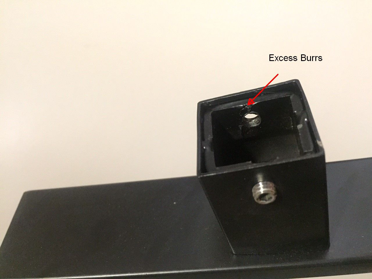
INTERNAL TAPPED HOLES ON NECK/STANDOFFS INSUFFICIENTLY DEBURRED POTENTIALLY
CAUSING
INTERFERENCE
Release: 13NOV2015
Affected Models: All
Description of Issue:
As of the release of this bulletin and for about 3%-5% of current inventory, users may have a difficult time fitting
the collar into the neck/standoff of the handle/pull during the installation process. The root cause of the problem
is that on the internals of the neck, there are 2 tapped holes (holes that have threads on them) of which Production
did not deburr them sufficiently causing remnants of the thread sticking out from the inside and causing obstruction
and interference when trying to fit the collar into the neck/standoff.
Solution:
Deburr the surface of the 2 holes internal to the neck with either a deburring tool, or using a small screw driver
to chip off the excess metal that is obstructing the collar.


J. KeyTiger Missing Accessories (Purchase Replacement Kits)
KTKIT-M6-01
KTKIT-M8-01


| Part Number | Model | Finish | Quantity Available | Price | Order Quantity | ||||||||||||||||
|---|---|---|---|---|---|---|---|---|---|---|---|---|---|---|---|---|---|---|---|---|---|
| KTKIT-M6-01 | Accessories | Spare accessories for KT3001-XXX-19-XX/C1, KT3014-XXX-3015-XX/C2 and KT2373-XXX-3015-XX | 0 |
|
|||||||||||||||||
| KTKIT-M8-01 | Accessories | Spare accessories for all except KT3001-XXX-19-XX/C1, KT3014-XXX-3015-XX/C2 and KT2373-XXX-3015-XX | 19 |
|
K. KeyTiger Sample Plate-Ring for Different Finishes
KT-FINISHES-01 (Sample Plate Rings)

| Part Number | Model | Finish | Quantity Available | Price | Order Quantity | ||||||||||||||||
|---|---|---|---|---|---|---|---|---|---|---|---|---|---|---|---|---|---|---|---|---|---|
| KT-FINISHES-01 | Accessories | Sample Plates for all Finishes | 0 |
|